DISCLAIMER: We are not responsible for anything wrong (including electric shocks, malfunctions, fires, accidents involving a soldering iron) that might happen during the assembly of the kit. Everything you do while assembling the kit is at your own risks.
Preparing for the build
We assume you know how to solder. If you don’t, please check these tutorials before proceeding — they are super helpful:]
EEVblog #180 – Soldering Tutorial Part 1 – Tools
EEVblog #183 – Soldering Tutorial Part 2 – Through hole soldering
The commonly accepted strategy for populating PCB’s is to add low profile components first (resistors, diodes, anything else axial), then proceed with higher profile parts (ceramic capacitors, IC sockets, etc), then finish with highest profile components (electrolytic capacitors, connectors, etc).
It’s also a good idea to wash the board a few times during the build: this allows you to better inspect solder joints quality and keep those microscopic solder whiskers away.
The bare dSPLIT PCB v.0.2:


Let’s get started:
Add 8 x 220 Ohm resistors. They are used for input & output protection.
Note: resistors are not polarized, but random resistors resistor orientation looks ugly 😉

Add one 1 Ohm resistor. (power filtering & protection):
Add 1 x 100K resistor (input pulldown) and 2 x 1n4148 diodes (input over & under voltage protection):
Note: diodes are polarized.

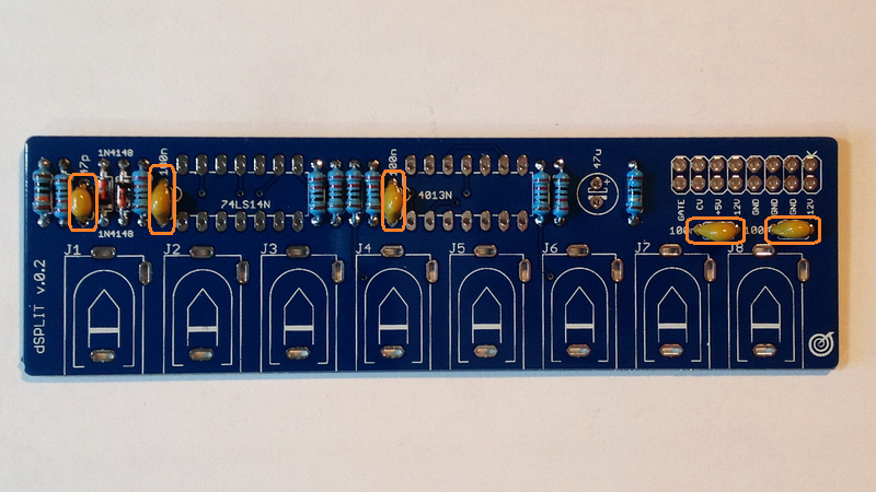
Add ceramic capacitors (not polarized).
1 x 47p (470) input EMI filtering capacitor.
4 x 100nF power filtering capacitors.

Add 1 x 47uF electrolytic capacitor (power filtering):

Then solder 2 x 14pin IC holders and 2×8 pin header (Eurorack standard power connector):

Add 8 x PJ-302M 3.5mm jack connectors:

Notice: Front panel is only 3hp width and we don’t need long pins, sticking from the bottom of the board. We suggest to cutout jack connectors pins to the length about 2mm BEFORE soldering. This trick helps to keep the bottom side of PCB free from possible scratches from cutters.

Power supply test:
It’s time to power up the module. dSPLIT is fully digital module, so we need only +5V.

Insert the IC’s:
1 x 74LS14N or 74HC14N Hex inverting Schmitt trigger.
1 x CD4013BE CMOS Dual D-type flip-flop
And, the panel:

Done!
